Aluminum Pump Support System

Design Criteria
Design Process
Iteration
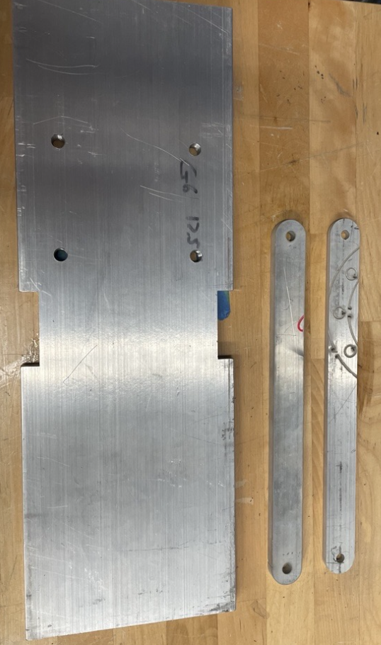
Final machined parts. Platform was machined using CNC mill, and arms machined using water jet.
Overview
To address flooding events near rivers and costal regions, a centrifugal pump system driven by a motor via belt and pulley system was designed to remove water from low areas. Our team was tasked with designing and manufacturing the support structure for the pump, consisting of a platform and connection arms. This project involved CAD modeling, hand calculations for deflection with stress concentrations, finite element analysis, and python script iteration. The physical machining was done with a CNC mill and a water jet.
1. Delivers 150 GPM to a height of 60’.
2. Platform bending deflection must be ≤3 mm.
3. Support structure should meet existing mounting hole pattern of 3.75” x 3” through removable clevis pins.
4. Support structure should have a minimum 1.5 factor of safety with respect to yielding or buckling loads.
5. Support structure must be corrosion and wear resistant at 1800 RPM
Our group began by representing and solving for all unknown forces, torques, and moments symbolically (see right for diagram), before iterating through various dimensions and attachment configurations to meet the design requirements. After a rough geometry was selected, failure analysis was then performed (using distortion-energy theorem), identifying critical stress locations and calculating factors of safety. Finite element analysis was then used to validate working designs before moving onto manufacturing.
To make the assembly lightweight while still fulfilling design criteria, a python script solving for factors of safety with respect to yielding and buckling was written. Initial platform dimensions, 17.5” x 6” x 1”, yielded very high factors of safety, but was too heavy for our optimal design. We slowly decreased thickness and width, removing material from the sides of the platform, until appropriate factors of safety and weight were achieved.
After the first pass of finite element analysis, the arm bearing less load was adjusted— thickness decreasing from .375” to .25”. This further reduced weight while maintaining appropriate factors of safety.
Initially, a series 7000 aluminum was chosen for its strength-to-weight ratio. An ANSYS plot of mass per unit of stiffness confirmed this choice, but due to availability and machinability, 6061 aluminum was chosen for manufacturing.
Machined Parts
Testing setup of final assembly, including existing mounting hole pattern
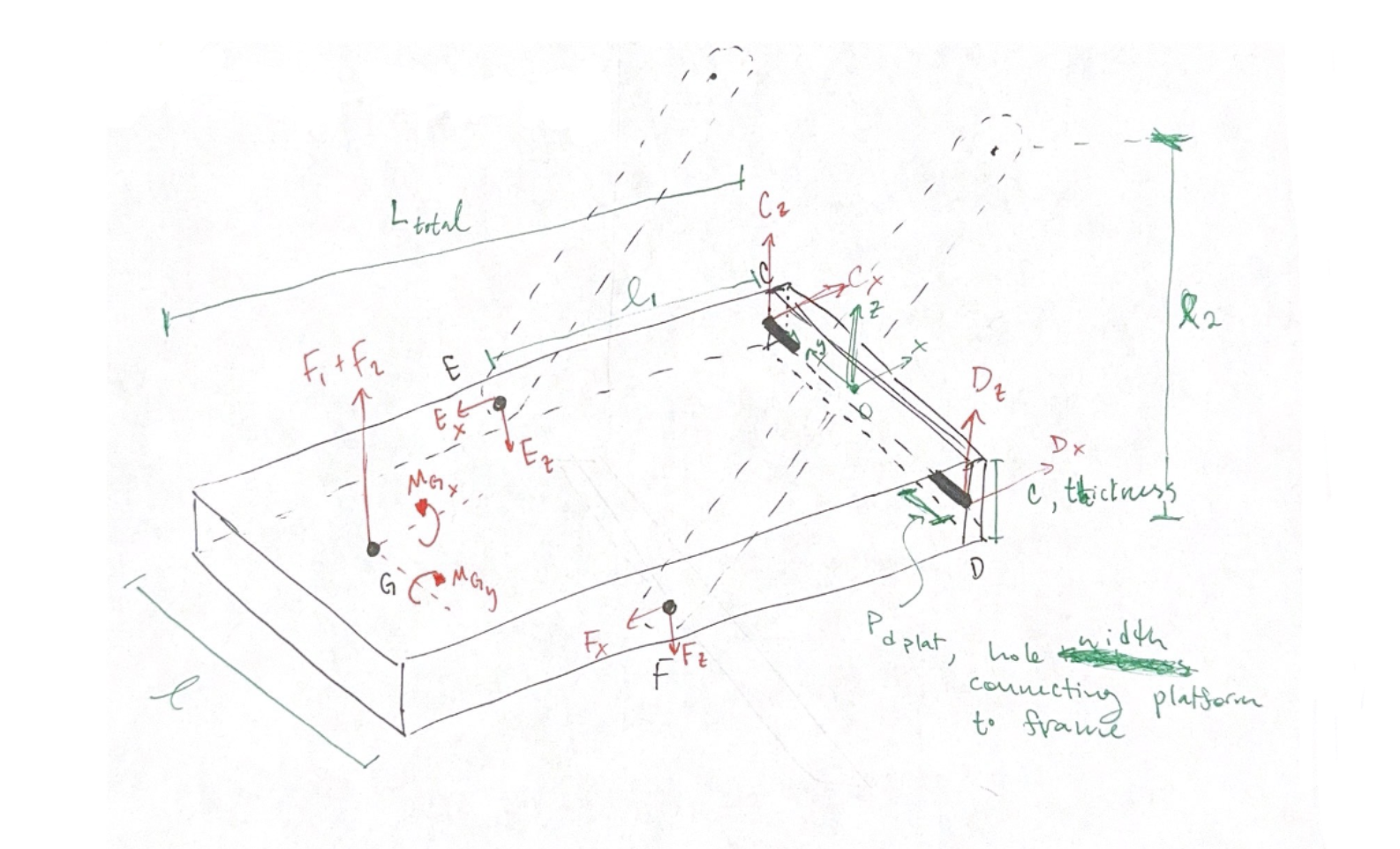
Preliminary diagram used to calculate maximum stress value and location. Values kept symbolic for python script iteration.

Early iteration of finite element analysis
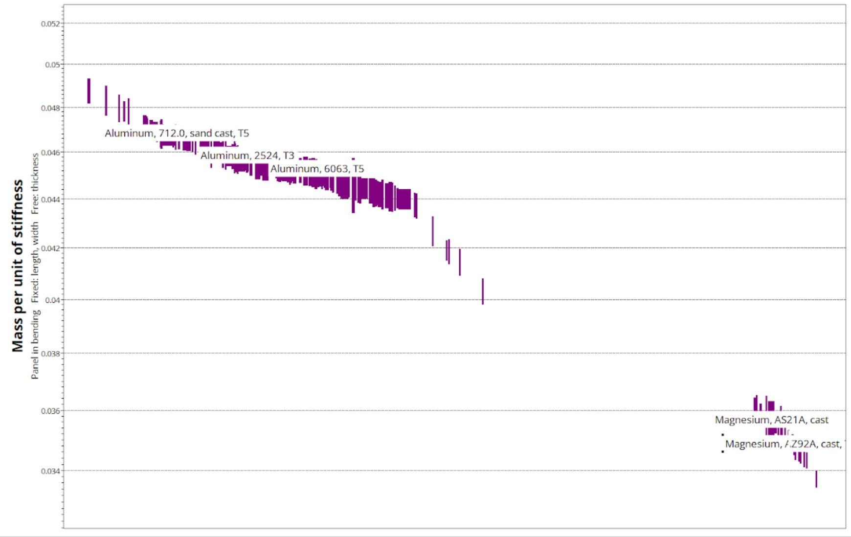
ANSYS material plot of mass per unit of stiffness
Final Design Drawings

Assembly drawing, including clevis pins, 1/4”x20 screws for arms, and 7/16”x20 steel screws for platform connection.

Final platform drawing


Final drawing of greater load-bearing arm (.375” in thickness)
Performance and Challenges
Our calculated factor of safety was higher than the actual part experienced, which allowed our system to withstand even up to 300N. Similarly, our simulated deflection was smaller than what we saw in the parts performance. This is expected with the higher factors of safety than necessary, with the addition of slight machining errors and variability in our parts, as well as the interface between parts and frame will not be as pessimistic as we predicted.
An unexpected challenge we faced was that we faced the improper dimensions of the arms. We calculated the length of the arms using the distance from the end of the platform to the holes, forgetting that their inset is connected to the bearings. We figured out this issue after already machining the arms. This required us to re-water jet these pieces to the correct size.
Final machined assembly attached to pump for testing