Pressure Vessel
I was tasked to design and machine a pressure vessel to hold 50-60cc of liquid at 750 psig. This project utilized material selection, CAD design, O-ring design, failure analysis, and fastener analysis.
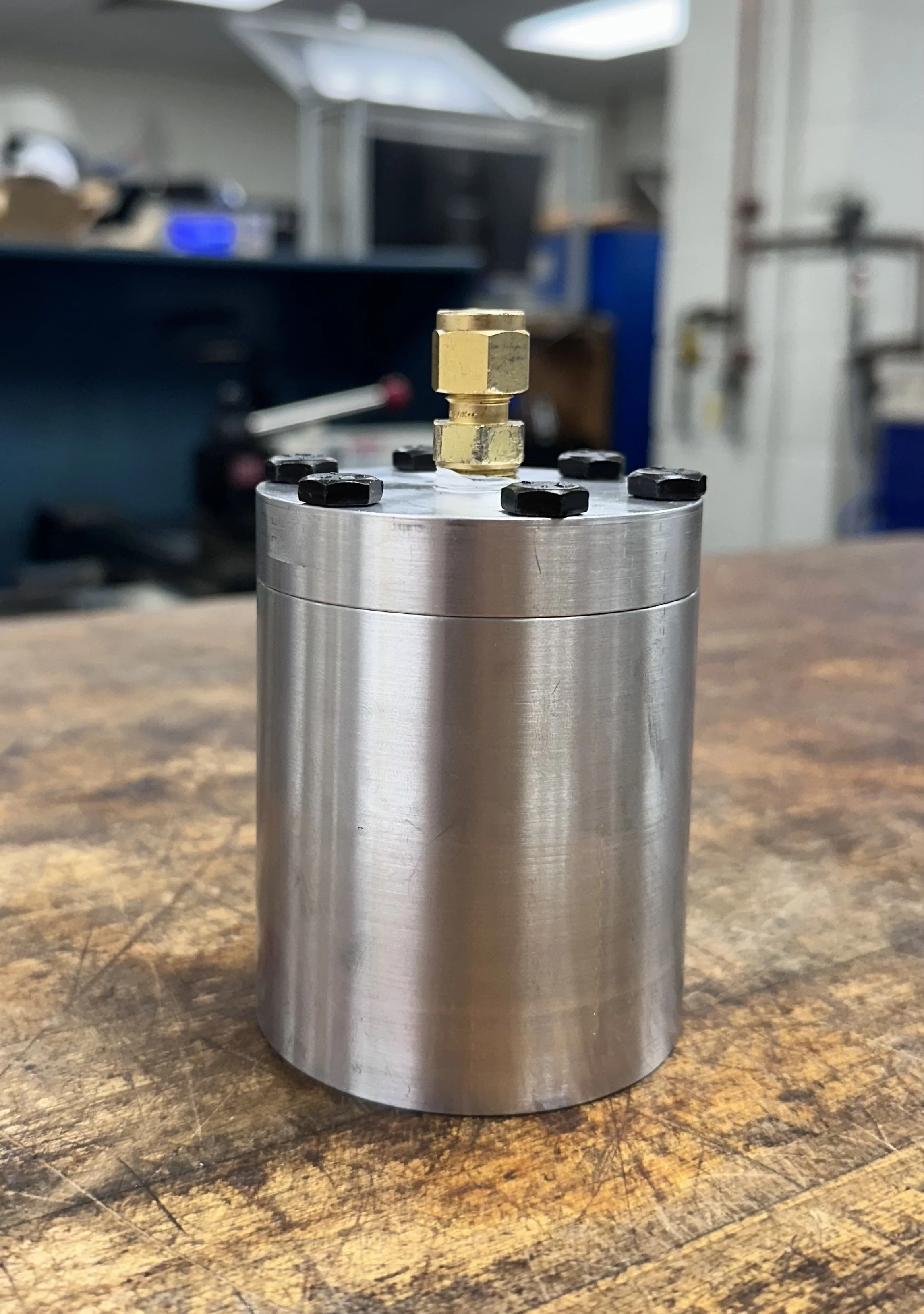
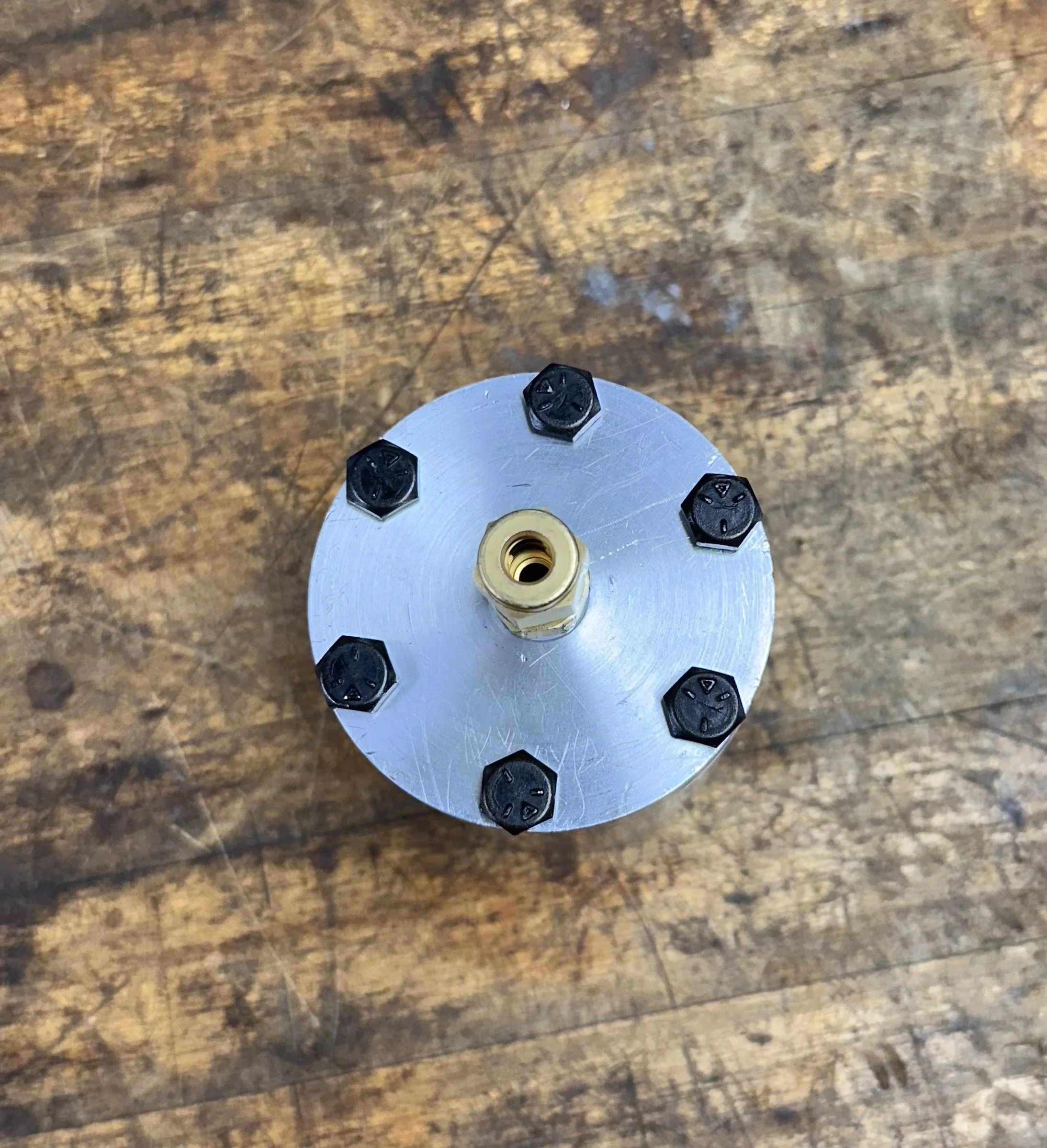
The design features a thick-walled aluminum base, a cap with an o-ring groove and 6 bolt holes, and a threaded port for a provided swagelock fitting. The entire vessel is 2.8” in diameter, with a 1.32” diameter hole bored 2.625” into the base (leaving .25” of material to withstand pressure). The threaded swagelock fitting is connected to the cap, with a .54” diameter, threaded hole in the center of the cap. To effectively seal, there is an o-ring that fits into groove on the bottom surface of the vessel cap. Finally, the cap is sealed to the base with six 1/4”x20 Grade 8 bolts 1” in length.
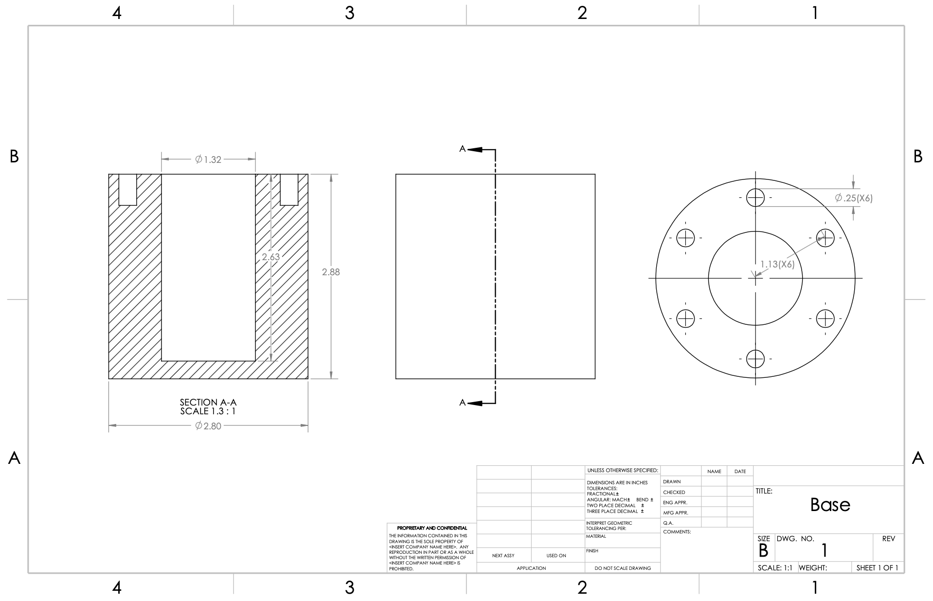
Final vessel base CAD drawing
Analysis for Design
To determine the best design parameters, we first selected a thick-walled pressure vessel design with arbitrary values, then carried out force and failure analysis to determine suitable dimensions.
The following equations were used for radial and tangential stress on a thick-walled pressure vessel:
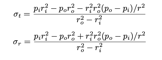
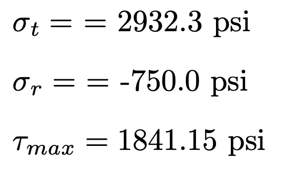
Substituting final dimension values (after iterating), the following stresses were calculated at r=ri, the critical stress location:
To determine a suitable O-ring that would seal our pressure vessel effectively, the following equations were used:
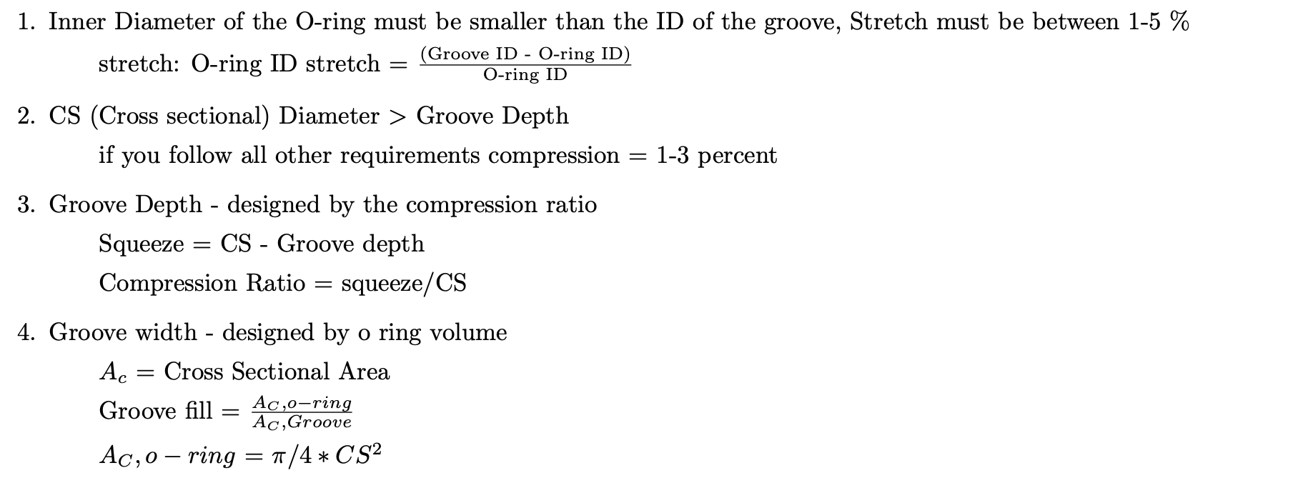
These equations yielding the following:
Stretch = 4.6%
When CR = .25%, Groove Depth = .0469”
CS = .070” > Groove Depth = .0469”
When Groove Fill = 65%, Groove Width = .1007”
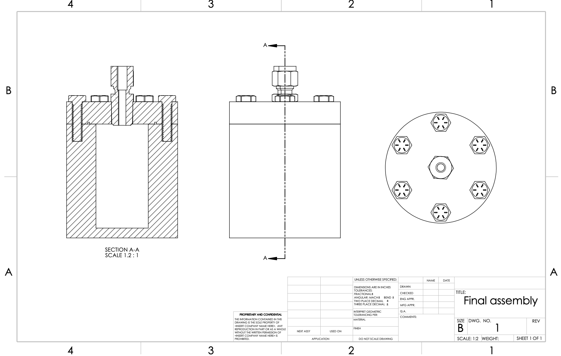
Final design assembly CAD drawing
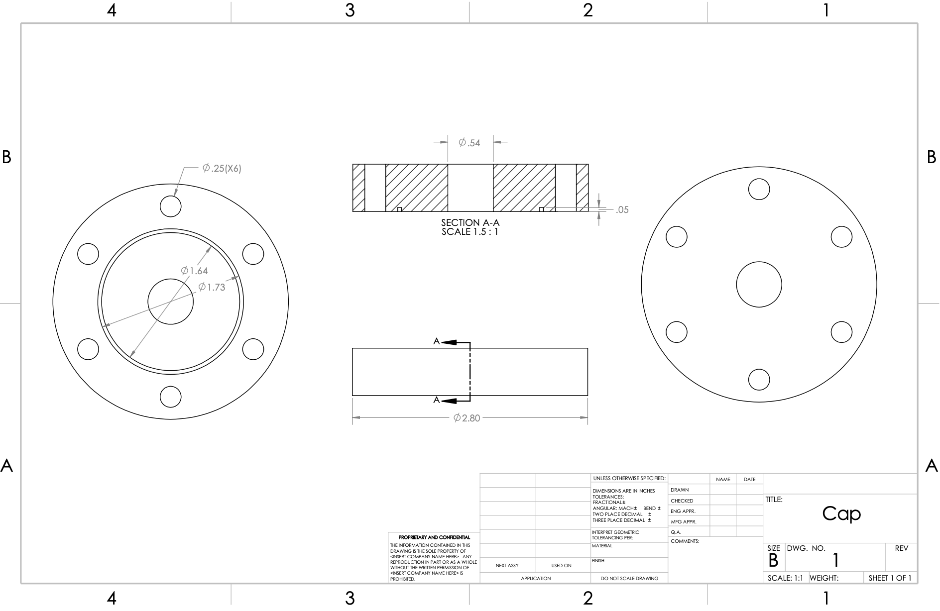
Final cap CAD drawing
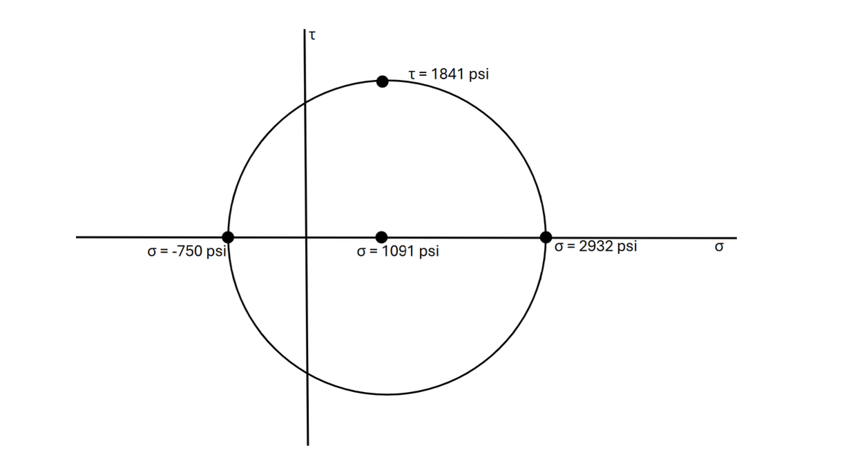
Mohr’s circle for pressure vessel design
Based on cost, machinability, strength, and availability, we selected Aluminum 6061 to build the pressure vessel. With a yield strength of 40,000 psi, this material yields a factor of safety (with respect to yielding), n=10.86.
O-ring Analysis and Selection
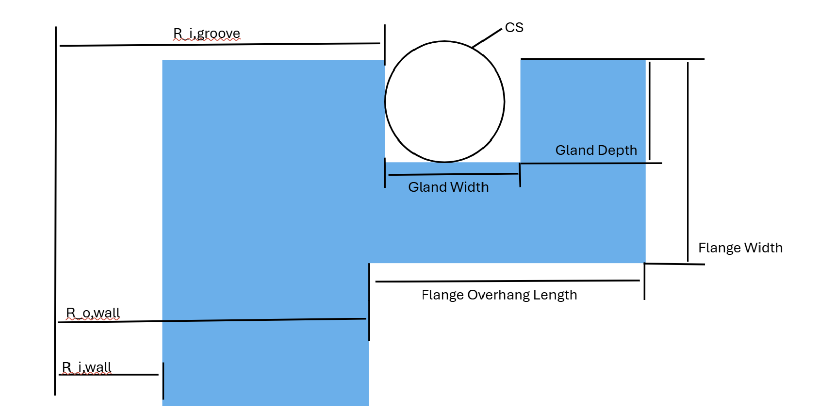
O-ring schematic, with key parameters labeled
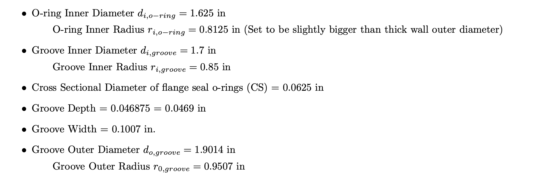
Solving for O-ring dimensions:
Based on these calculations, an O-ring with 1/16” CS, 1 5/8” ID, 1 3/4” OD was selected.
Fastener Analysis
To analyze our fasteners, we began by selecting SAE grade 5 bolts for both availability and strength (Sp=85×103 psi). We determined that dm ≤ .35", as the distance between the edge of the flange and the outer diameter of our O-ring groove is .4". Additionally, we found an approximate tensile area, At, with the following equation:
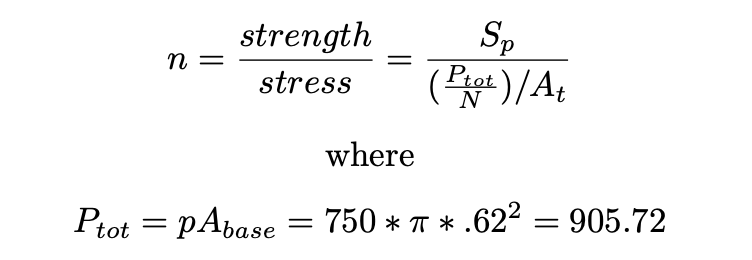
This equation, assuming at most 6 bolts and a factor of safety of 3, determined that the smallest At for our purposes is .00533 in^2. This provided us with a lower limit, meaning the smallest bolt we can select is 4X40 UNC. The largest, given the aforementioned constraint, is 5/16 X 18 UNC. Considering these factors, we determined the optimal bolt is 1/4 X 20 UNC grade 5 bolts.
Additionally, The length of the bolt must be at least .81875 in. This was rounded to the closest available grade 5 steel bolt, L=1.0 in. The screws we selected are McMaster-Carr 92865A541.
Machining
Machining was done using a CNC lathe, horizontal bandsaw, and an Atrump Knee Mill.
First, stock was faced using the CNC lathe. Also using the lathe, the outer diameter was machined to our drawing specifications. Next, the center hole was drilled and tapped for the 1/4” NPT Swagelock fitting. The CNC mill was used to drill 2” holes for the bolts into the body.
Next, using a horizontal bandsaw, the cap was removed from the base. The lathe was used to clean up both faces of this cut. The cut was made with some clearance so that the cut could be adequately cleaned up. The center hole was also bored to the proper dimensions.
Finally, the O-ring groove was programmed and cut using the Atrump Knee mill. This cut was sanded, and the 6 drilled bolt holes were tapped.
Performance
With high factors of safety, our pressure vessel outperformed our design criteria, withstanding 1000 psig. It held 58 cc of liquid, within the specified range.