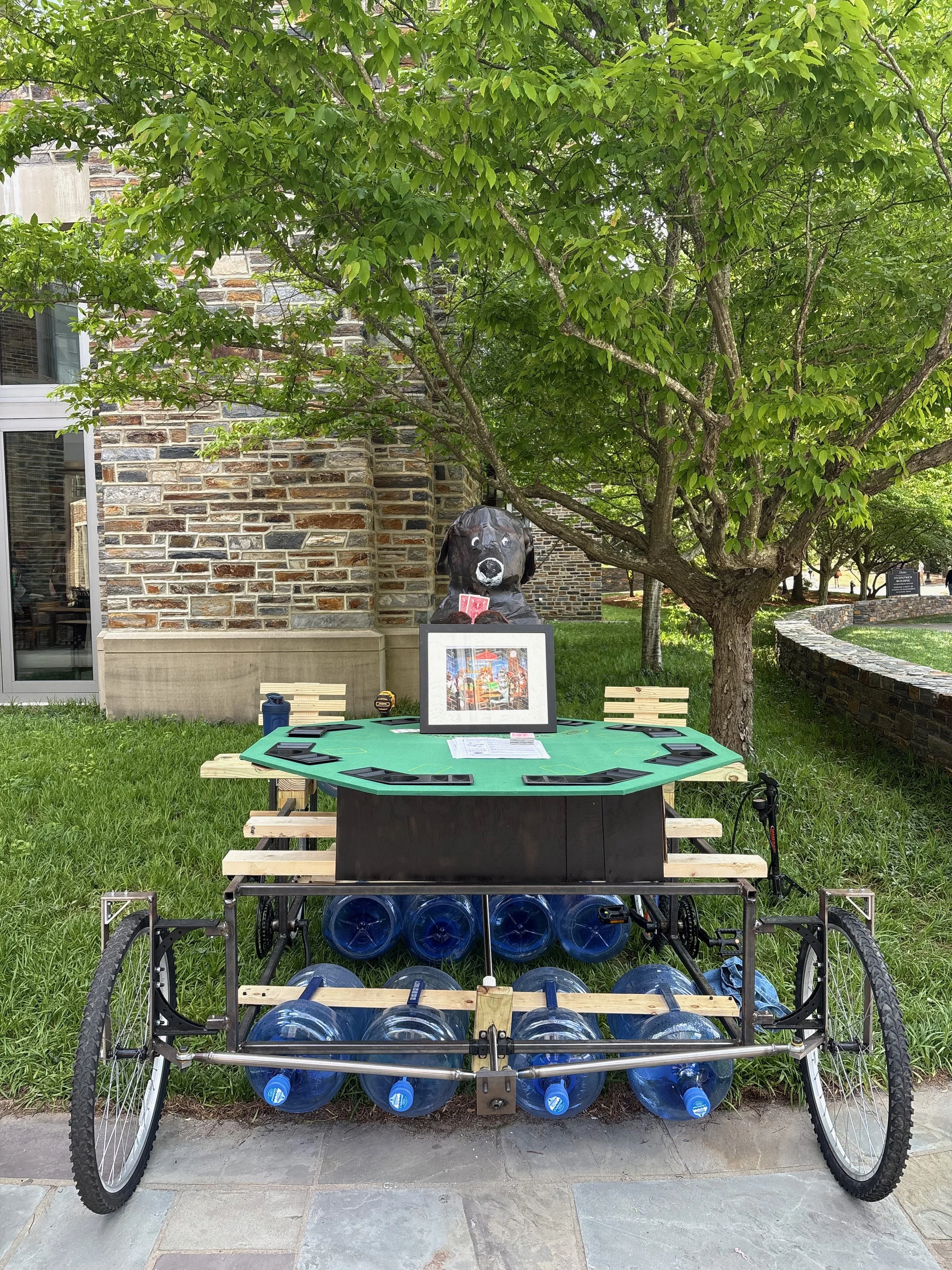
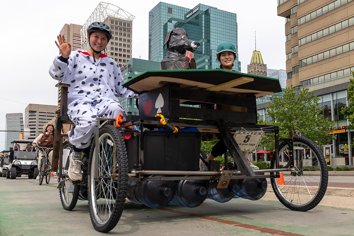
Kinetic Sculpture Race: Dogs Playing Poker
Skills
SolidWorks, Finite Element Analysis
Structural & Failure Analysis
Fatigue & Static Stress Calculations
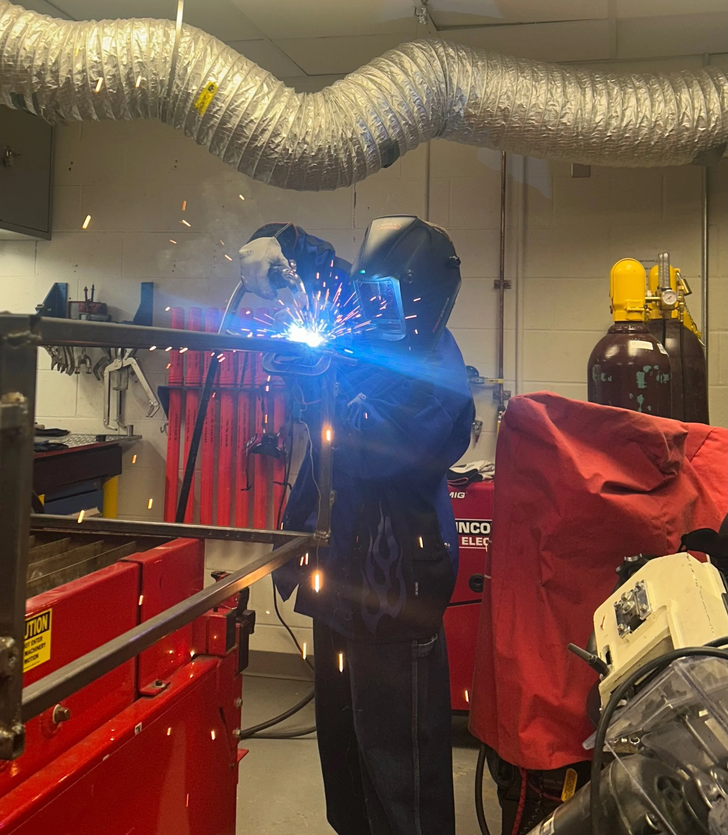
Welding
CNC Milling
Steering & Drivetrain Design
Sculptural Fabrication
Components
Frame
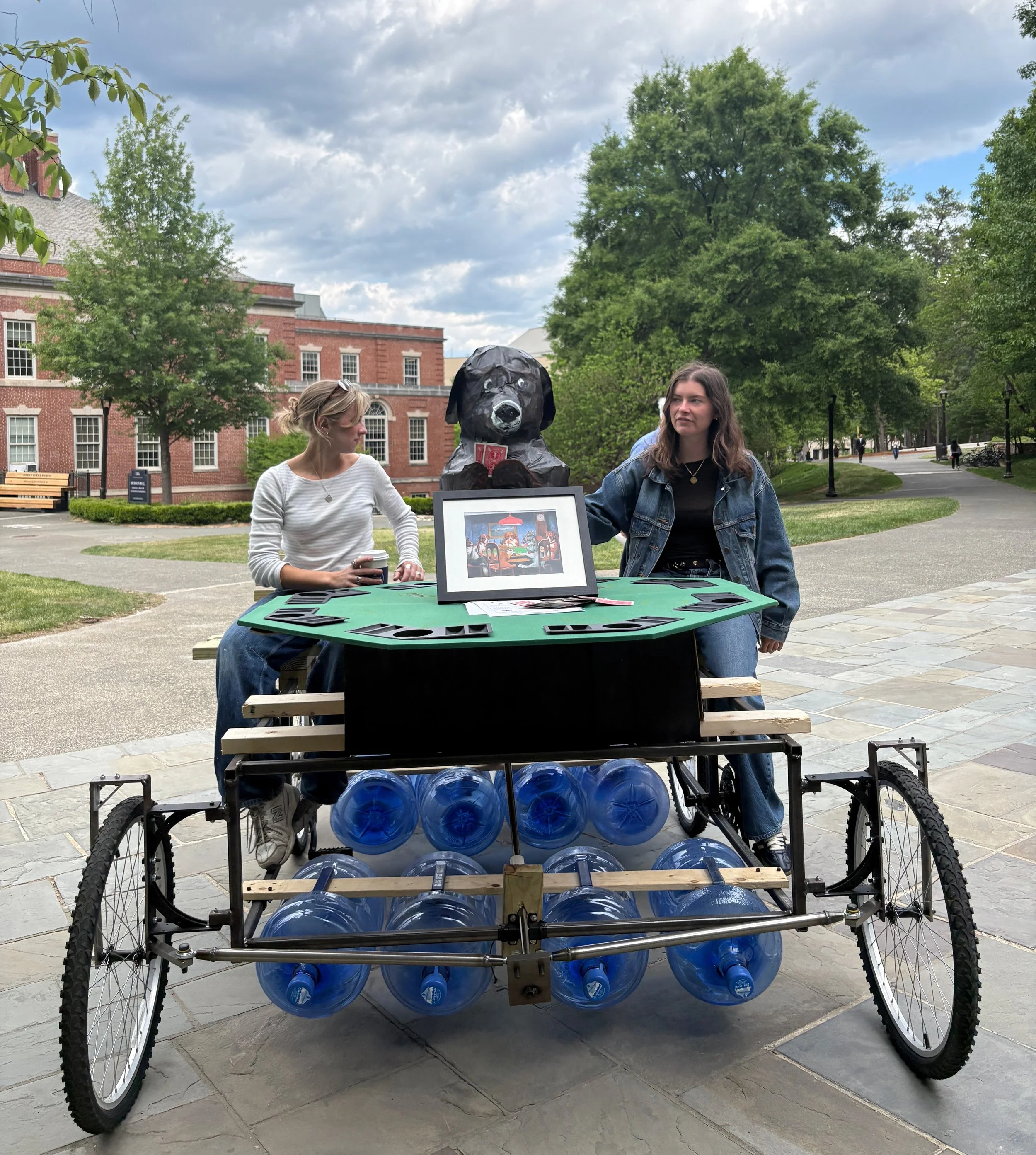
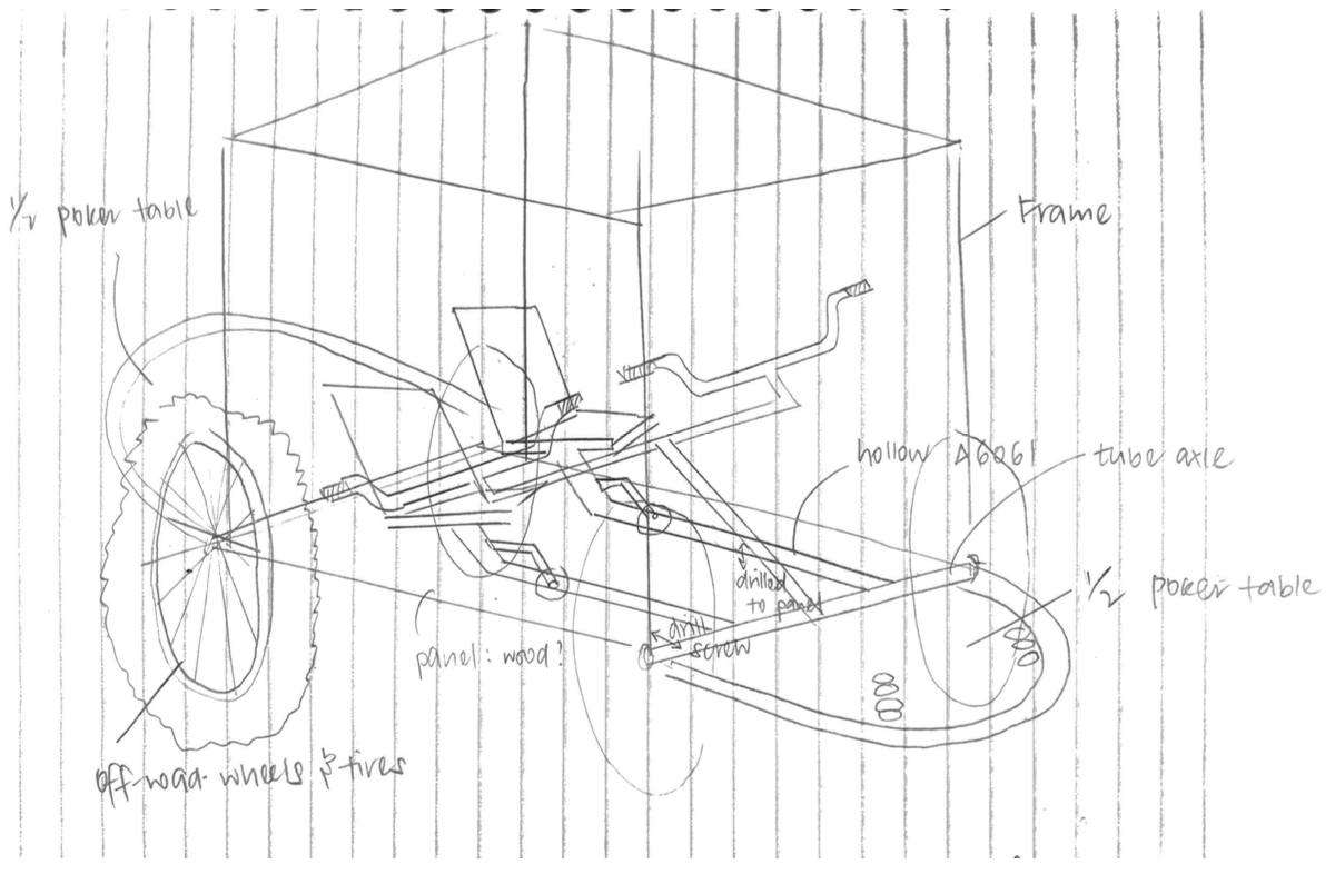
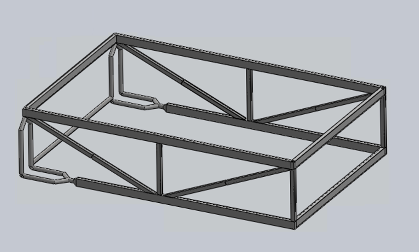
The frame carries two riders plus the sculpture's full weight (~300 lbs) and would undergo considerable cyclic loading.
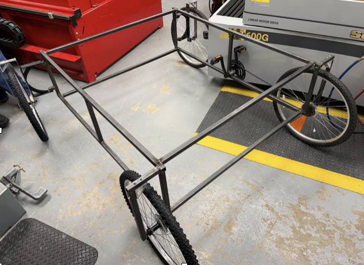
I compared four frame geometries by FEA and hand calculation—eventually a double-layer square-bar frame in 304 stainless steel was chosen due to a static factor of safety of 5.3 and a weight under 100 lbs.
AVAM rules and our personal design goals made the frame design choice clear. AVAM mandates <8% wetness of the pilots, meaning they would need to sit considerably above the flotation line of the water jugs. Also, we wanted a functional poker table at arm’s length. Both of these criteria, in addition to factor of safety under static and cyclic loads, informed the double frame design decision.
To reduce welding and machining time, the trusses on the sides were removed after hand calculations and FEA determined that factor of safety was still appropriate.
Steering
Drivetrain
Materials
304 Stainless Steel
Bicycle-derived wheels and drivetrain components
Repurposed 5-gallon water jugs (flotation)
Foam, plywood
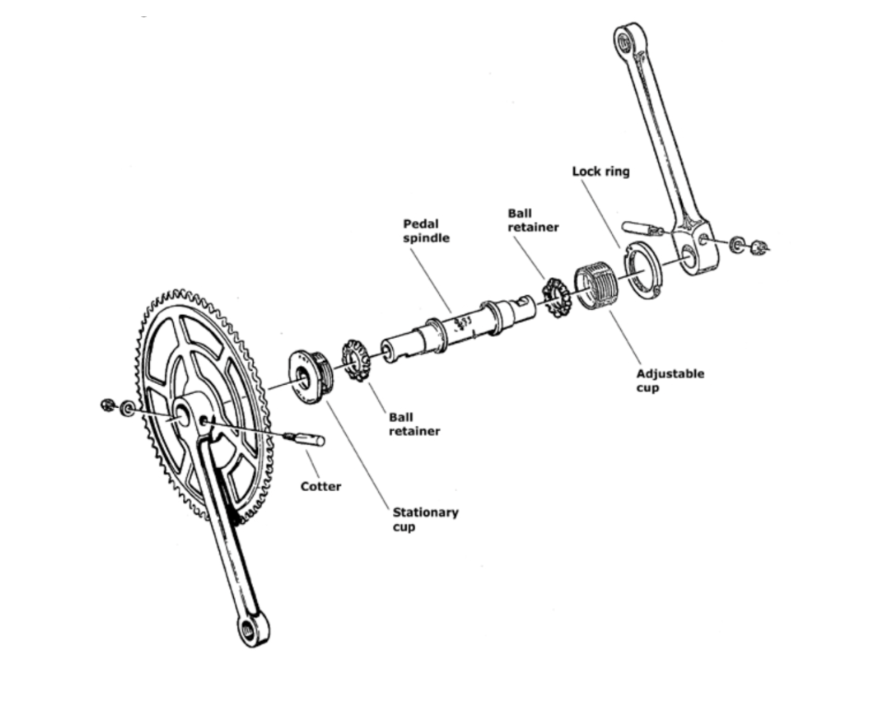
Drivetrain components can be identified in the expanded view. To meet race standards, motion is producing only mechanically. The rider’s pedaling action drives the crankset, chain, and connected mechanisms to translate rotational input into continuous kinetic motion for the sculpture.
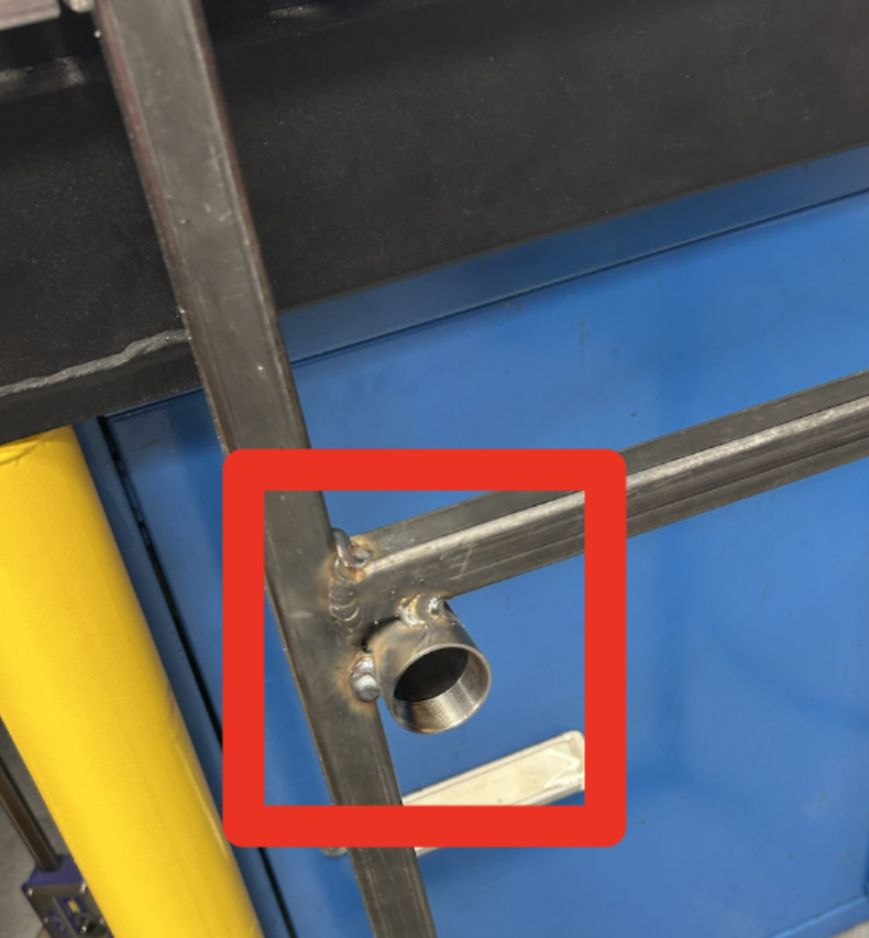
A cylindrical steel shell was welded directly onto the structural frame to securely house and support the pedal spindle. This component serves as the central bearing interface for the rotating crank system. The drivetrain alignment and load transfer between the rider’s input force and the entire assembly depend on this shell. By welding the shell to the frame, any lateral movement under torque is prevented and the spindle maintains concentric rotation.
Floatation
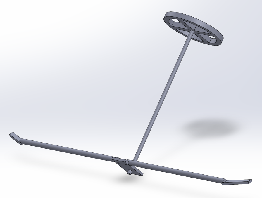
The steering system utilizes a custom tie-rod assembly designed to maximize ease of adjustment. The assembly consists of a combination of heim joints, threaded bungs, and steel pipe sections, allowing for fine-tuned alignment while maintaining structural integrity under load. This set-up resembles common go-cart steering systems.
The steering linkage uses Heim joints for multi-axis articulation and minimal binding, with welded connections at structural interfaces and threaded bungs for adjustable, serviceable tie rods. Machined steel plates form the steering arms and a central base welded to the shaft; the arms sit at 45° to keep the Heim joint clear of the kingpin axis for optimal torque transfer. Custom tie rods — right- and left-hand threaded for self-adjustment — connect the arms to the base, with the shaft stabilized against shift by a rod-and-collar assembly.
To enable steering, the wheels must be able to rotate at least 35°. The front of the frame was updated to allow this, with wheels protruding at the sides. To allow for rotation, heavy duty shelving brackets were sourced and connected to cantilever beams with long pins and washers.
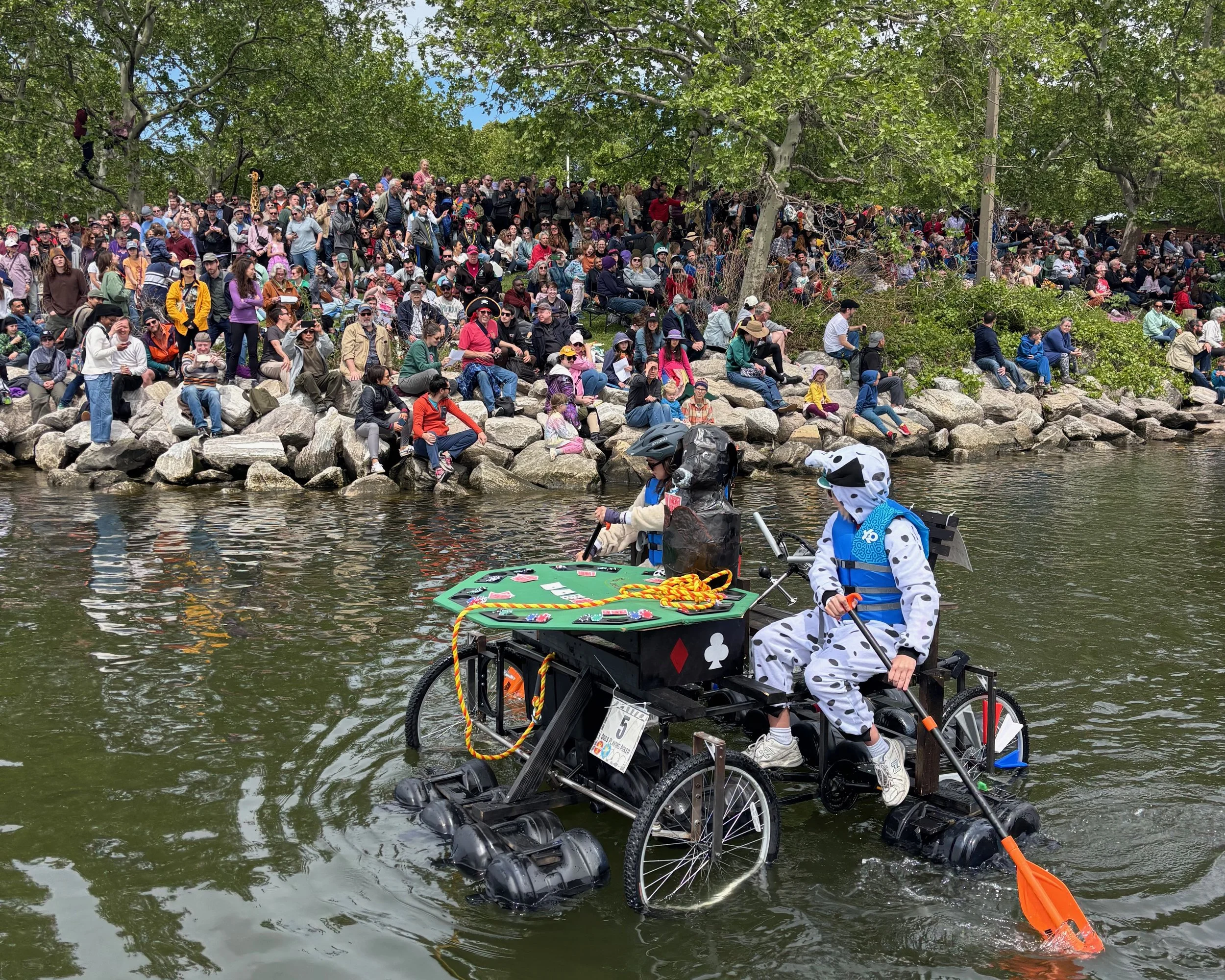
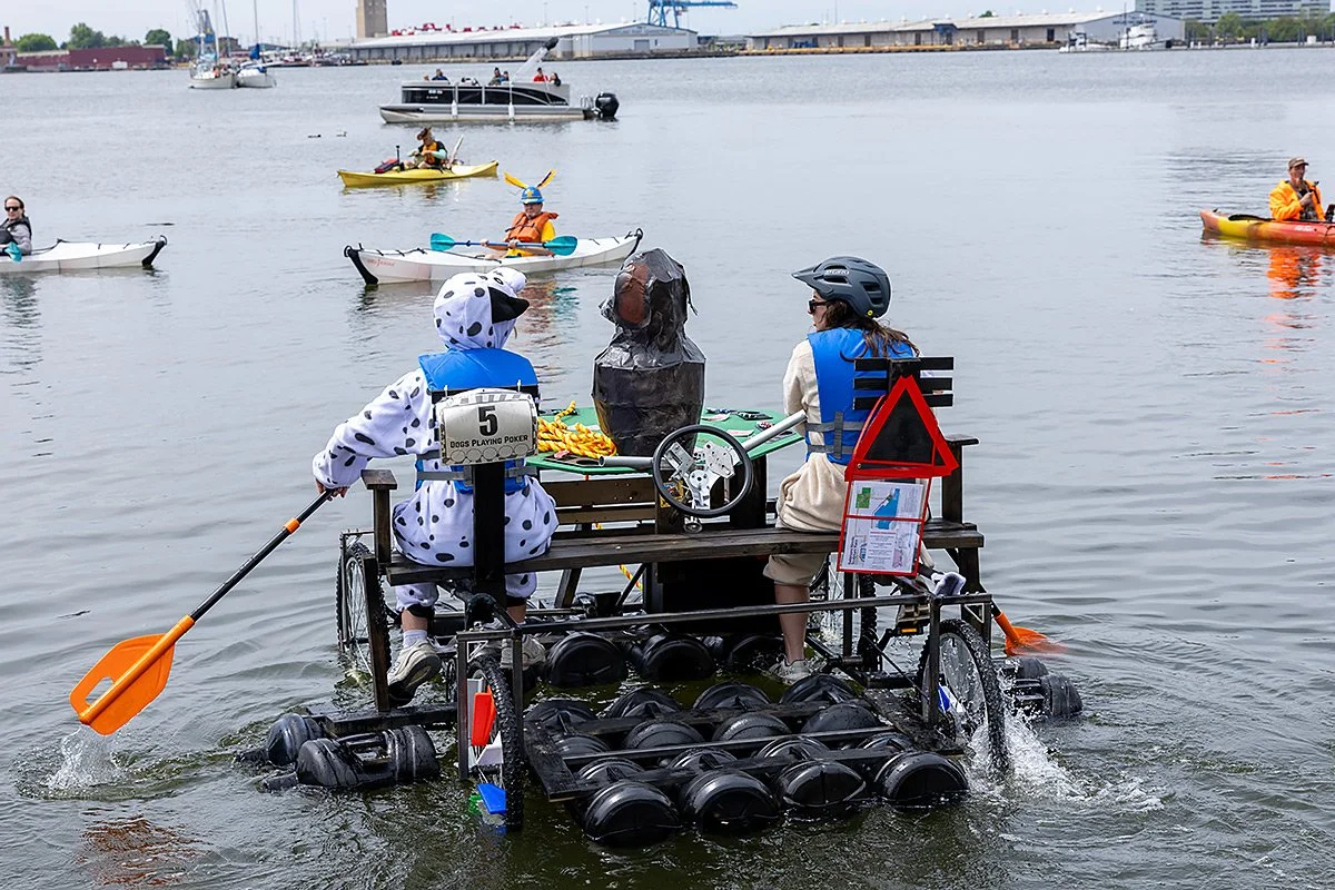
The flotation system supports the full weight of vehicle and riders during water sections while resisting excessive tilt or submersion. The final design uses 20 sealed 5-gallon plastic water jugs arranged in 4 large and 2 small arrays mounted to the frame's underside and sides. Testing showed each jug provides roughly 31 lbs of buoyant force, giving a total capacity of ~620 lbs — well above the 450 lb design requirement, with the margin covering dynamic loading, uneven weight distribution, and water disturbance.
12 jugs mount permanently along the base in groups of 4, providing primary vertical lift; two detachable side arrays and one detachable front array (2–4 jugs each) attach only for the water leg and act as stabilizers. Each array is built from a 2x4 run through the jug handles and bolted to the steel frame via brackets. This jug-based approach was chosen for its modularity, low cost, and ease of fabrication.
Breaks
Braking is handled by two independent, lever-actuated mechanisms, one per rear wheel, avoiding a single point of failure. Each brake uses a wooden dowel lever positioned between the rider's legs, pivoting on a single screw mount and spring-loaded to stay off the wheel at rest. Pulling the lever rotates a 3D-printed, Velcro-covered brake pad into the wheel, generating friction without excessive wear. Mirrored on both sides, the system is low-cost, lightweight, and easy to manufacture while still giving riders reliable control across the race's varied terrain.